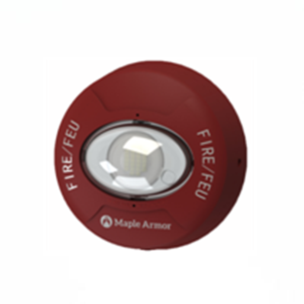
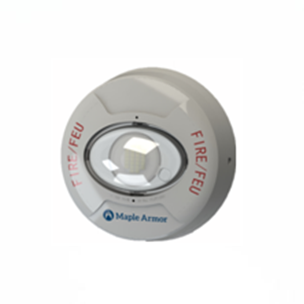
The FW962R/W Horn Strobes and FW982R/W Strobes are a family of multi-candela visual and audible signal appliances with light sources generated from white LED, listed according to UL 1971, UL 1638, UL 464, ULC-S525 and ULC-S526 for indoor use. The LED light source offers superior performance, including low power consumption and long operating life. Six levels of light output are selectable. Figure 1 shows relative light outputs in horizontal and vertical dispersion from strobes mounted on walls/ceilings.
SPECIFICATION
|
Operating Voltage |
16 to 33 VDC/FWR |
||||||
|
RMS Operating Current @16 Vdc(mA) |
|
130cd |
105cd |
85 cd |
50 cd |
35 cd |
20 cd |
|
FW962R FW962W |
164 |
126 |
85 |
55 |
47 |
30 |
|
|
FW982R FW982W |
156 |
119 |
80 |
49 |
43 |
28 |
|
|
RMS Operating Current @16Vfwr (mA) |
|
130cd |
105cd |
85 cd |
50 cd |
35 cd |
20 cd |
|
FW962R FW962W |
187 |
158 |
102 |
66 |
58 |
38 |
|
|
FW982R FW982W |
154 |
150 |
97 |
61 |
53 |
35 |
|
|
Sound Level (dBA) |
Voltage |
16V dc/fwr |
24V dc/fwr |
33V dc/fwr |
|||
|
UL Reverberant |
77 |
81 |
85 |
||||
|
ULC Anechoic |
85 |
88 |
91 |
||||
|
Directional Characteristics |
Horizontal Axis |
Angle |
OSPL (dBA) |
||||
|
0° (ref) |
0 (ref) |
||||||
|
± 44° |
-3 |
||||||
|
± 54° |
-6 |
||||||
|
± 90° |
-10.5 |
||||||
|
Vertical Axis |
Angle |
OSPL (dBA) |
|||||
|
0° (ref) |
0 (ref) |
||||||
|
± 52° |
-3 |
||||||
|
± 55° |
-6 |
||||||
|
± 90° |
-12 |
||||||
|
Effective Light (cd) |
130, 105, 85, 50, 35, 20 (See Figure 3 for candela selection) |
||||||
|
Operating Temperature |
0° C to 49° C (32° F to 120° F) |
||||||
|
Operating Humidity |
0 to 93% RH |
||||||
|
Horn Pattern |
Temporal 3 |
||||||
|
Strobe Pattern |
1 flash per second |
||||||
|
Wire Size |
12 to 18 AWG |
||||||
|
Location |
Indoor wall/ceiling |
||||||
|
Compatible Model |
FW951 Sync Module, FW106 / FW106C FACP |
||||||
INTALLATION
1. Mount the FW900 base onto a 4x4 electrical box, see Figure 2.
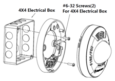
Figure 2. Base Installation
2. Set the strobe signal level to the desired setting. See Figure 3.
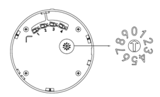
Figure 3. Candela Selector
3. Connect the wires. See Figure 4 and Figure 5.
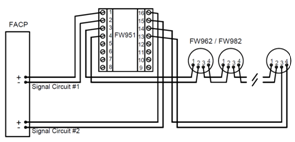
(a) Class A Circuit without Audible Silence Feature
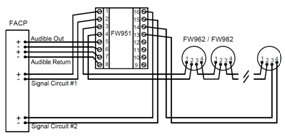
(b) Class A with Audible Silence Feature
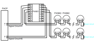
(c) Class B without Audible Silence Feature
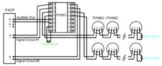
(d) Class B with Audible Silence Feature
Figure 4. Wiring Diagram with FW951 Sync Module
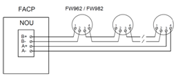
(a) Class A Circuit
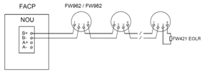
(b) Class B circuit
Figure 5. Wiring Diagram with FW106/FW106C FACP
4. Combine the (horn) strobe with base – Align the (horn) strobe onto the base then and twist it in clockwise.
5. Test for proper operation. Initiate this unit from the connected FACP and observe for proper operation.
MAINTENANCE
Scheduled inspection and operational test should be carried as per requirement set out by Local Authority Having Jurisdiction.
Return the device for reparation if it fails to alarm during testing. Do not disassemble the detector without permission.

官方公众号

智能家居公众号
400 008 9119
qnxf@jbufa.com
市场部公众号
官方公众号
版权所有© 2017 青鸟消防股份有限公司 冀ICP备10006876号-2 网站地图 · 法律申明
Tel:400 008 9119